
Expert Guide to Overhead Crane Installation: Standards and Safety Procedures
The mechanical and electrical fit-out of heavy lifting equipment inside manufacturing halls and large warehouses is an extremely sensitive engineering challenge. Fixing calculations and rail alignment leave no margin for error, since any mistake can lead over time to premature wear of the steel structure or to catastrophic collapse accidents that threaten the safety of the facility and its workers. Overhead crane installation goes beyond lifting a metal bridge and placing it over the runways. It is a complex engineering procedure that begins with a structural survey of the supporting structure, passes through millimetre-precision rail straightness adjustment and the connection of smart control panels, and ends with static and dynamic load tests certified to international standards such as CMAA, FEM and OSHA.
How Are Overhead Cranes Installed Safely and Professionally?
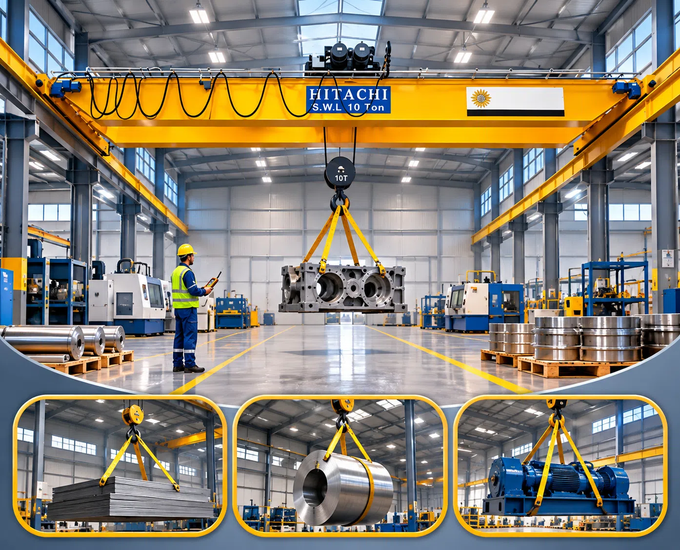
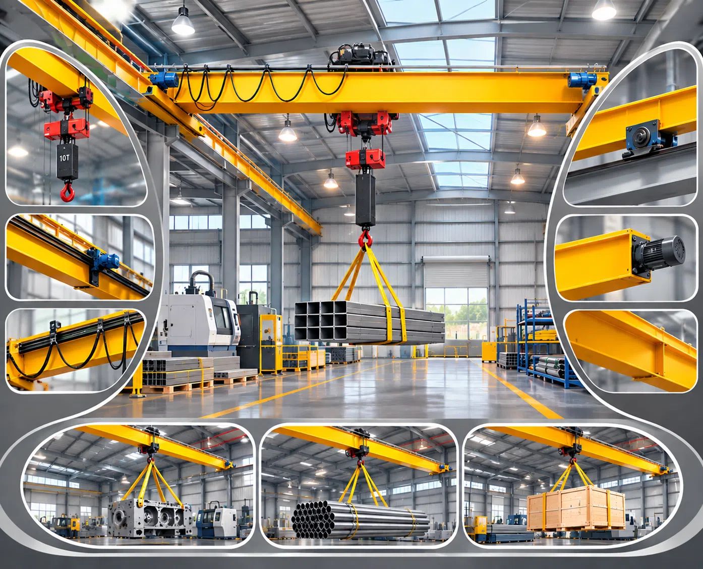
Overhead crane installation follows an engineering protocol that begins with a structural audit of the runway beams and building columns, followed by mechanical lifting and precise fixing of the crane bridge and end carriages, laser alignment of the rails and verification of their levelness, connection of the insulated conductor bars, setting of the limit switches and emergency brakes, and concludes with load tests at 125% and 110% and the issue of official calibration certificates.
Applying this strict execution sequence delivers strategic results in the field:
- Preventing creep forces and diagonal travel (Crane Skewing), which eat away at wheel flanges and destroy the runway rails.
- Distributing dynamic loads evenly across the hall columns without exposing the structure to unplanned torsional stresses.
- Obtaining approval from the regulatory authorities, the civil defense and the occupational safety and health offices without any technical remarks.
Phase One: Structural Audit and Preliminary Safety Preparations
Occupational safety requires a comprehensive inspection of every element of the site before heavy lifting equipment enters the hall:
1. Assessing the Condition of Runway Beams (Runway Beam Inspection)
You must confirm that the supporting steel or concrete structures can withstand the vertical and horizontal reaction forces and the braking forces generated by the crane moving at full capacity. This includes checking beam deflection (Deflection) and verifying the span (Span) dimensions with laser precision, to make sure there is no buckling or column deviation beyond the tolerances permitted by CMAA Spec 70/74.
2. Lifting Plan & Site Safety
Prepare an engineering drawing showing the positions of the mobile installation cranes (Mobile Cranes), their capacities and boom angles. The installation area must be fully secured with warning barriers, with pedestrians barred and no production lines operating beneath the work path, and crews must wear double safety harnesses and personal protective equipment (PPE) designated for work at great heights.
3. Component Verification and Visual Inspection of the Equipment
Inspect the crane bridge, the end carriages (End Carriages), the travel motors and the hoist unit, and review the certificates of origin and the non-destructive testing (NDT) of welds, to make sure no part was damaged or bent during shipping and transport.
Phase Two: Mechanical Fixing and Laser Rail Alignment
This phase is the beating heart of the installation. Every extra millimetre of rail misalignment translates directly into friction noise and destructive operating vibrations:
1. Span & Rail Alignment
Laser scanning devices and optical theodolites are used to set the distance between the centrelines of the two parallel rails. International standards require that the deviation in rail span must not exceed the specified tolerance in mm, and the gaps at rail joints must be set at a mechanical bevel angle that reduces wheel shocks and allows for thermal expansion.
2. Bridge & End Trucks Assembly
The end trucks are lifted onto the rails and temporary safety stops are fixed. The box or lattice girder is then lifted and connected to the end trucks with high-tensile steel bolts (Grade 8.8 or 10.9). These bolts are tightened with calibrated torque wrenches (Calibrated Torque Wrenches) to achieve full squareness between the bridge and the runway and to prevent any diagonal deviation of the crane while it travels.
3. Lifting and Assembling the Hoist Trolley and Setting Wheel Clearance
The hoist is lifted and the cross-travel trolley (Trolley) is mounted over the bridge girders. The clearance between the wheel flanges and the rail head is set to match the manufacturer's catalogue (usually between 2 and 4 mm), and mechanical end-of-travel buffers fitted with polyurethane dampers or hydraulic cushions are installed to absorb any accidental impact.
Phase Three: Electrical Connections and Smart Safety Systems
Overhead cranes need a stable power supply and control circuits that guarantee an immediate response to operator commands:
1. Installing Insulated Power Lines (Conductor Busbars)
Fix copper conductor tracks protected by insulating enclosures (with a protection rating of no less than IP23/IP54) along the length of the runway, and equip the crane with spring-loaded current collector arms that ensure continuous contact without any electrical sparking, preventing power interruptions during long travel.
2. Hanging Cross-Travel Cables (Festoon Cable System)
Install the flexible cable track (C-Rail Festoon) along the crane bridge to feed the hoist trolley with smooth motion that prevents the electrical wires from being stretched or pinched during cross travel.
3. Programming Frequency Inverters (VFD) and Adjusting Sensors
Calibrate the frequency inverters of the hoisting and travel motors to provide smooth start-up and deceleration that eliminates load sway (Anti-Sway), and set the dual limit switches (Limit Switches) that automatically cut the raising, lowering and travel motions before the moving parts reach danger points.
Comparative Analysis: Certified Engineered Installation vs. Unspecialized Ad Hoc Installation
The following points show the fundamental technical and operational differences between using accredited engineering firms and relying on unskilled labor:
- Rail alignment accuracy and wheel integrity: Engineered installation relies on precise laser instruments that guarantee the rails are parallel, preventing wheel flange wear and rubbing against the rails, whereas ad hoc installation causes the crane to leave its track or the wheels to wear and crack within a few months.
- Tightness of structural bolts: Experts use calibrated torque wrenches according to engineered tightening schedules, whereas unskilled labor relies on estimated manual tightening, which causes bolts to loosen under vibration and bridges to fall.
- Safety system and load limiter setup: The specialized team calibrates the digital load cells and the limit switches and tests the response of the electromagnetic brakes, whereas manual installation ignores programming these sensors, which raises the likelihood of cable breakage and dropped loads.
- Official documentation and the civil defense file: Certified installation provides a complete technical file including material inspection certificates, weld test reports and approved load test records, which ad hoc labor lacks, leading regulators to refuse the facility's license.
Phase Four: Commissioning, Load Testing and Official Calibration (Commissioning)
No overhead crane may be put into actual production until it has passed a strict package of field tests:
- No-Load Testing: Run the hoisting and lowering motions, the cross travel of the trolley and the long travel of the bridge for several consecutive cycles, to confirm that the radio controls work, that the gearbox sound is smooth, and that the emergency stop button (E-Stop) is effective.
- Static Load Test - 125%: Lift a load equal to 125% of the crane's rated capacity and hold it suspended 10 to 20 cm above the ground at mid-span for 10 continuous minutes. The aim is to measure the deflection and compare it with the permitted limits, and to confirm that the bridge returns fully to its straight condition as soon as the load is lowered.
- Dynamic Load Test - 110%: Operate all crane motions, up, down and travelling, while carrying a weight equal to 110% of its maximum capacity, to test the strength and efficiency of the electromagnetic brakes and confirm they stop the load within a fraction of a second without any mechanical slip.
How Do You Ensure a Certified and Safe Installation of Your Overhead Cranes with "Al Manarat Al Monerah"?
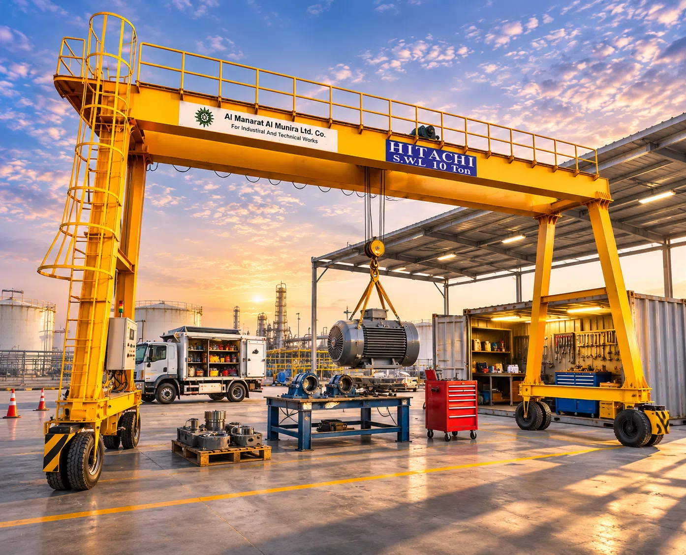
Al Manarat Al Monerah (almanratalmonerah.com) leads the supply, design and engineering of industrial lifting equipment in the Kingdom of Saudi Arabia, Egypt and the Middle East, offering an integrated range of execution services that ensure the highest levels of safety and reliability:
- Specialized structural and field study: Inspection of runway beams and hall columns using optical and laser instruments, and dynamic calculations to confirm the building can safely accommodate the overhead crane loads.
- Certified engineering installation crews: Supervision by an elite team of specialized engineers and technicians equipped with the latest lifting equipment, torque wrenches and measuring instruments, to ensure precise installation that complies with CMAA, FEM and ISO codes.
- Supply and integration of genuine power and control systems: Equipping the crane with fully insulated conductor tracks, encrypted digital radio control systems and smart frequency inverters that provide smooth acceleration to prevent load sway.
- Load testing and calibration certificates: Carrying out static and dynamic load tests with certified calibrated weights, and issuing official engineering inspection certificates and reports that qualify the equipment for immediate operation and ensure its compliance with civil defense requirements.
- Genuine spare parts readiness and preventive maintenance contracts: Local warehouses stocked with motors, brakes, lifting chains, steel wire ropes and electronic boards to secure regular preventive maintenance that protects your facility from unexpected downtime.
Al Manarat Al Monerah lets you contact its engineering consultants directly to arrange a site visit to your facility and discuss the technical details of your overhead crane installation, ensuring the safety of your facility and multiplying its productive capacity for decades to come.
Frequently Asked Questions About Overhead Crane Installation
How long does it take to install an overhead crane and make it ready for field operation?
The mechanical and electrical installation of a standard overhead crane (single or double girder up to 10 tonnes) over a ready runway beam takes between two and 4 working days, including commissioning tests and field calibration. Large projects that require laying entirely new runway beams may take a week or more, depending on the architectural dimensions of the building.
Can an overhead crane be installed on existing steel columns without a structural assessment?
Installing any overhead crane without a certified structural study of the hall columns is strictly prohibited. Overhead cranes generate shear forces, bending moments and large lateral dynamic loads from the acceleration and braking of the trolley and bridge, so it must be verified by engineering analysis that the column sections and concrete foundations can bear these stresses, to prevent deformation of the building.
What is the procedure if the laser rail test shows a deviation in the crane span?
The rail fixing bolts and rail clamps (Rail Clamps) in the defective area are released, and the rail is re-aligned horizontally and vertically using neutral steel levelling shims (Shims). The laser measurement is then repeated until the deviation falls within the internationally permitted limit in mm, before the bolts are finally tightened to the specified torque.
Read also: Why You Need Specialist Experts When Installing Factory Cranes